If you would like to perform your own wheel bearing replacement, you should be aware that improper removal and installation can result in some premature damage to the actual bearings and other components. To avoid any mistakes, you should be careful in following these recommended steps in replacing single-row wheel bearings which exist in most passenger cars and light trucks.
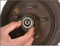
Step 1. Disassemble wheel-end components. In this step, you should remove several components such as the tire and wheel assembly, disk brake caliper, dust cap, cotter pin, adjusting nut and washers. It is important to note though, that you should strictly follow the procedures as lifted from your manufacturer’s specific recommendations. After this, you must pull the rotor/hub assembly towards you in order to loosen the outer bearing cone assembly, and once loose, take it out. Then, pull the rotor/hub assembly off the spindle, and the inner bearing, cone assembly, inner and outer cups and the seal should come with it. And before you remove the inner bearing cone assembly from the rotor/hub assembly, you should use seal puller to remove the seal. You can throw out the seal after you have removed it. Also remove the inner and outer cup from the housing with a cup driver or mild steel bar.
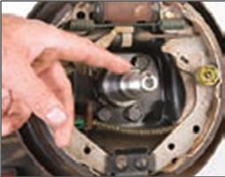
Step 2. Clean and inspect hubs and spindles. Get rid of the old lubricant from the rotor/hub assembly and spindle and clean them with mineral oil or kerosene. Check the spindle for some possible wear. In cleaning, use a fine file, wire brush, emery cloth or honing stone and remove any debris, nicks or burrs. Check your carmaker’s recommendation for the acceptable amount of spindle wear. Apply a light grease coating on the cone seats, as they will make installation easier and will prevent any fretting.
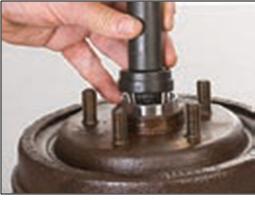
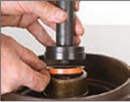
Step 3. Install the cups. Press or drive the new inner and outer cup into the hub/rotor assembly until they are firmly placed against the hub shoulders. To do this, you can use a cup driver or a mild steel bar. Work cautiously so you don’t damage the cup surface, and remember to not use a bearing cone assembly to drive a cup.
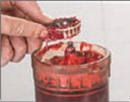
Step 4. Lubricate the cone assembly. Apply some grease in the inner bearing cone assembly. You may use a mechanical grease packer for this. Then, place the bearing cone assembly into the grease packer funnel with the small end down. Using a conical retainer, plug the bore of the large end of the bearing cone assembly. Then, with some force, press down on the conical retainer. This will cause the grease to be forced between the rollers, cage and cone. Then, spread some excess grease on the outer part of the bearing cone assembly. Next, put some grease in the hub cavity between the inner and outer cups. Then, apply a liberal coating of grease to the hub cap inner wall, as this layer will repel moisture and keep the grease in the inner and outer bearing cone assemblies.
Step 5. Install the grease seal. This must be done when there are leaks or when the bearings are being repacked or replaced. Thus, install the seal after you install the inner bearing cone assembly. Make sure that the lips are correctly pointing to the direction closest to the carmaker’s specification. Also, use the correct seal installation tools.
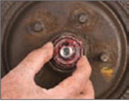
Step 6. Install the rotor/hub assembly. Move the rotor/hub assembly back over the spindle, and be careful to not cause damage to the seal. Apply grease to the outer bearing cone assembly, similar to the procedures mentioned in Step 4. Then, install the outer bearing cone assembly, the washer, and the adjusting nut on the spindle.
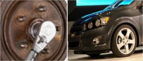
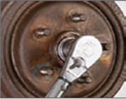
Step 7. Adjust the Bearing. Using a torque wrench, tighten the adjusting nut to around 50 ft. lbs., while turning the rotor. Then, back off the adjusting nut one full turn, and re-torque the nut to 10 ft. lbs. Then, back it off again and adjust the nut a quarter turn. Lastly, lock the nut with a new cotter pin.
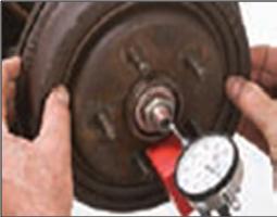
Step 8. Check the Bearing Adjustment. Measure the end play using a dial indicator. Then, place the indicator base near the center of the hub/rotor as much as you can. While the indicator tip is against the end of the spindle, set the indicator at zero. Then, grasp the rotor at 90 and 270 degrees angle (that’s your three o’clock and nine o’clock in more common jargon). Then, push the rotor in while oscillating and read the dial indicator. Then, repeat this except you should “pull” this time. The bearing end-play is equal to the total indicator movement, and the standard measures are between 0.001” – 0.007”. If the reading goes beyond this, you should re-adjust the bearing (repeat Steps 7 and 8). Finally, reinstall all components as recommended by your vehicle manufacturer.
Remember that while these tips may be very useful, they must be performed with much caution. Don’t improvise with tools and procedures that are not recommended, as they may cause unwanted injury to you and damage to your car. And if you would like to shop conveniently for car parts online, check out Autopartsway.com. We have a huge collection of high quality auto parts with great discounts that can be delivered right to your doorstep.


